Toyota Process Flow Diagram
Get Toyota Process Flow Diagram Background. Business process flow diagrams solution extends the conceptdraw diagram bpm software with rapiddraw interface, templates, business process diagrams examples and numerous libraries based on the bpmn 1.2 and bpmn 2.0 standards, which give you the possibility to visualize equally easy. A logical dfd focuses on the business and how the business operates.
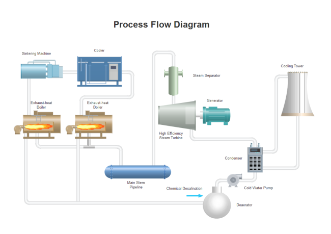
A pfd does not show minor components.
For all of the diagrams discussed in this chapter, there are no. A process flow diagram (pfd) is a diagram commonly used by chemical engineers in the process design of petroleum refineries, natural gas processing plants, petrochemical and chemical plants and other industrial facilities to indicate the general flow of plant process streams and equipment. Where or when does the process start? The process flow diagram (pfd) is a critical component of process design.

0 Response to "Toyota Process Flow Diagram"
Post a Comment